Can a Flex PCB Quote With Stand Harsh Environments?
Flex PCB Quote With Stand Harsh Environments
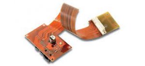
The ability to withstand harsh environments is a crucial factor in the success of a rigid-flex or flex PCB. This type of circuit board has been used by medical device manufacturers to help patients with a variety of conditions, such as heart disease, arthritis, and diabetes. However, in order to ensure the durability of a flex pcb quote, certain design elements should be considered during the quoting process.
To begin, a rigid-flex or flex PCB must be made of the appropriate raw materials. The most common are polyimide (PI), polyethylene naphthalate (PEN), and polyetherimide (PEI). Polyimide is the most popular due to its combination of advantageous electrical, mechanical, chemical and thermal properties.
In addition to the base raw material, a flex PCB must contain copper conductors, dielectric layers, and adhesive layers. In some cases, the flex circuit may also require special materials such as conductive adhesives and solder mask. The type of surface finish is also important. A tin or soft gold finish will provide a solderable surface and prevent copper oxidation. Finally, the circuit must be coated with a protective coating. This could be a polyimide or epoxy layer, a coverlay, or a photo-imaged dry film.
Can a Flex PCB Quote With Stand Harsh Environments?
Depending on the application, a flex PCB might need to withstand various environmental stresses and vibrations. These stressors might be caused by vibrations, bending, or high temperatures. To minimize these stresses, a flex circuit should be designed with large, curved angles. Conductors should be routed perpendicular to the overall bend axis, which eliminates stress points that can damage copper circuits. Lastly, a flex circuit should be reinforced along the inside bend radius using tear guards to prevent tears. In addition, it is important to stagger traces and keep them from touching.
The impedance of a flex circuit is another critical design factor. During the quoting process, engineers should discuss their flex circuit’s impedance requirements with a CM to ensure that the design will perform properly when it is manufactured. Proper flex layer stackup and impedance control will improve signal transmission efficiency while reducing loss and jitter.
Lastly, a flex circuit should use the highest quality copper possible. This can be achieved by selecting a maximum copper weight of 2 oz or higher. Moreover, the circuit should be built with an adequate number of layers to avoid deformation or distortion. Additionally, the CM should inspect the circuit during production to verify that it meets IPC-610 and IPC-EIA J-STD-001 standards for assembly.
A stiffener is a layer of rigid material such as FR4 that is added to specified areas on a flex PCB to increase its overall thickness. This increases the tensile strength of the circuit, which can withstand more bending and twisting. It also reduces the amount of heat that is dissipated during the forming and soldering processes. This feature is especially important for high-speed data communication and RF signals. It also provides extra protection against electromagnetic interference (EMI). In addition, a stiffener can be used to strengthen joints and increase the reliability of the circuit’s connections.